
라즈베리파이 - LCD, 카메라
LCD
연결 방법
5V(Pin 2) - 5V
GND(Pin 39 or Pin 9) - GND
SDA (Pin3/GPIO2) - SDA
SCL (Pin5/GPIO3) - SCL

sudo raspi-config입력 후, interface option -> i2c 통신 enable 설정을 해준 후, sudo reboot 해준다.
nano 명령어로 파일을 생성한후, python3 명령어로 실행 시켜주자.
이때 코드는 아래와 같다.
import smbus
import time

# Define some device parameters
I2C_ADDR  = 0x27 # I2C device address, if any error, change this address to 0x3f
LCD_WIDTH = 16   # Maximum characters per line

# Define some device constants
LCD_CHR = 1 # Mode - Sending data
LCD_CMD = 0 # Mode - Sending command

LCD_LINE_1 = 0x80 # LCD RAM address for the 1st line
LCD_LINE_2 = 0xC0 # LCD RAM address for the 2nd line
LCD_LINE_3 = 0x94 # LCD RAM address for the 3rd line
LCD_LINE_4 = 0xD4 # LCD RAM address for the 4th line

LCD_BACKLIGHT  = 0x08  # On
#LCD_BACKLIGHT = 0x00  # Off

ENABLE = 0b00000100 # Enable bit

# Timing constants
E_PULSE = 0.0005
E_DELAY = 0.0005

#Open I2C interface
#bus = smbus.SMBus(0)  # Rev 1 Pi uses 0
bus = smbus.SMBus(1) # Rev 2 Pi uses 1

def lcd_init():
  # Initialise display
  lcd_byte(0x33,LCD_CMD) # 110011 Initialise
  lcd_byte(0x32,LCD_CMD) # 110010 Initialise
  lcd_byte(0x06,LCD_CMD) # 000110 Cursor move direction
  lcd_byte(0x0C,LCD_CMD) # 001100 Display On,Cursor Off, Blink Off
  lcd_byte(0x28,LCD_CMD) # 101000 Data length, number of lines, font size
  lcd_byte(0x01,LCD_CMD) # 000001 Clear display
  time.sleep(E_DELAY)

def lcd_byte(bits, mode):
  # Send byte to data pins
  # bits = the data
  # mode = 1 for data
  #        0 for command

  bits_high = mode | (bits & 0xF0) | LCD_BACKLIGHT
  bits_low = mode | ((bits<<4) & 0xF0) | LCD_BACKLIGHT

  # High bits
  bus.write_byte(I2C_ADDR, bits_high)
  lcd_toggle_enable(bits_high)

  # Low bits
  bus.write_byte(I2C_ADDR, bits_low)
  lcd_toggle_enable(bits_low)

def lcd_toggle_enable(bits):
  # Toggle enable
  time.sleep(E_DELAY)
  bus.write_byte(I2C_ADDR, (bits | ENABLE))
  time.sleep(E_PULSE)
  bus.write_byte(I2C_ADDR,(bits & ~ENABLE))
  time.sleep(E_DELAY)

def lcd_string(message,line):
  # Send string to display

  message = message.ljust(LCD_WIDTH," ")

  lcd_byte(line, LCD_CMD)

  for i in range(LCD_WIDTH):
    lcd_byte(ord(message[i]),LCD_CHR)

def main():
  # Main program block

  # Initialise display
  lcd_init()

  while True:

    # Send some test
    lcd_string("Hello Sir",LCD_LINE_1)
    lcd_string("Yes u did it",LCD_LINE_2)

    time.sleep(3)

    # Send some more text
    lcd_string("Have a nice Day",LCD_LINE_1)
    lcd_string("Metacamp",LCD_LINE_2)

    time.sleep(3)

if __name__ == '__main__':

  try:
    main()
  except KeyboardInterrupt:
    pass
  finally:
    lcd_byte(0x01, LCD_CMD)
lcd를 제어해주기 위한 코드이다.
위에 써있는 것처럼 Hello Sir부터 Metacamp 등등의 문구들이 출력될 것이다.
node-red로 프로그래밍 해보자
팔렛트에서 pcf857x를 검색해 나오는 node-red-contrib-iiot-rpi-pcf857x를 설치하자.
구성은 다음과 같이 inject와 iiot module - LCD 이 두개만 사용하면 된다.
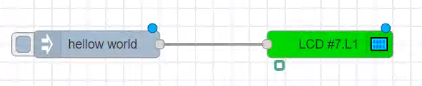
LCD-Display(hd44780)의 설정사항은 아래와 같다.
LCD-Type: 1602(2*16)
Device-Type: PCF8574
I2C-Address: 27H(3FH)
Linne-Number: 1
Right-Align
Fill: Custom Font 0
카메라
sudo raspi-config -> interface Option -> Legacy Camera -> enable -> sudo reboot
만약 위 방법으로 카메라가 켜지지 않는다면, raspistill -o test.jpg를 입력해주자.
카메라를 연결할 땐 전원을 끈 상태로 연결해야한다.
팔레트에 camerapi를 검색하면 나오는 node-red-contrib-camerapi를 설치해준다.
구성
inject와 take photo node write file을 연결해주면 된다.
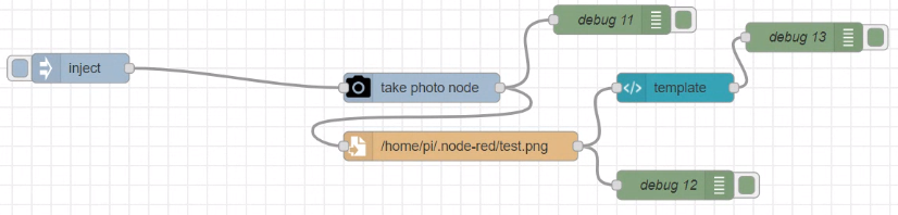
camerapi - take photo의 설정사항은 다음과 같다

write filed도 설정을 변경해준다.
파일명: path - /home/유저네임/test.png
동작: 파일에 추가
디렉토리가 존재하지 않는 경우에 작성
Enoding: 기본값
연결
시리얼 통신
유선 연결(USB, RS422, SPI, RFC 등)을 통해서 물리적으로 연결패킷 설정이 필수적ccp와 udp의 차이?udp가 빠르다..ccp는 왕복 필요 -> 포트가 하나 필요 -> 느리다udp는 보내기만 한다. -> 포트가 2개 필요 -> 빠르다
일반적으로 udp를 많이 사용한다. 빨라야하기 때문
mqtt는 ccp 기반 통신이다. ccp 통신에 payload나 등등을 얹은 것.
헤더와 페이로드를 다 보내는 것. 페이로드는 크기가 변할 수 있다.씨리얼 통신은 보통 고정된 패킷으로만 보내야 빠르기 때문에 크기가 거의 고정된 것이나 다름 없다.
ccp와 udp 처리량 차이
ccp는 한 포트에서 정보를 보내고 처리하고 헤더, 페이로드에 따른 작업을 해야하고 보내줘야하므로 한 번에 처리할 수 있는 처리량이 적다.
udp는 두 포트를 사용함으로써 처리량이 많다고 할 수 있다.
ㅇ
ㅇ
ㅇ
ㅇ
ㅇㅇㅇ
ㅇ
ㅇ
ㅇ
ㅇ
ㅇ
ㅇ
ㅇㅇ
ㅇ
ㅇ
ㅇㅇ
ㅇ
ㅇ
ㅇ
ㅇ
ㅇ
ㅇ
'TIL > 디지털트윈' 카테고리의 다른 글
| 07.07 디지털 트윈 부트캠프(OT) 5일차 (0) | 2023.07.07 |
|---|---|
| 07.06 디지털 트윈 부트캠프(OT) 4일차 (0) | 2023.07.06 |
| 07.04 디지털 트윈 부트캠프(OT) 2일차 (0) | 2023.07.04 |
| 07.03 디지털 트윈 부트캠프(OT) 1일차 (0) | 2023.07.03 |
| 06.09 디지털 트윈 부트캠프 39일차 (0) | 2023.06.09 |


댓글